Family Creation: Annotation or Detail Item?
I recently had a request for a fake column grid annotation graphic for use in drafting views but also for use in typical details that need to document conditions at multiple different grid line intersections. This seemingly simple task quickly turned into the Revit nightmare of circling around different methods of creating the family, coming across a roadblock, and circling back again only to discover you’re back where you started with hours lost and nothing to show for it. In an attempt to prevent others from having to go through what I did, and in an effort to explain the issue clearly to Autodesk so hopefully Revit can be improved I am going to go through the process in detail here.
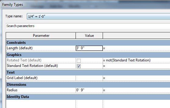
First attempt was to make the family a detail item. This was the only way (that I knew of at the time) for the grid line part of the family to be stretchable with grips. The grid head (circle with a label inside) needed to scale (so it would be the same size printed regardless of view scale) so I made the circle have a “Radius” type parameter and made 26 different types (one for every architectural and engineering scale I could think of):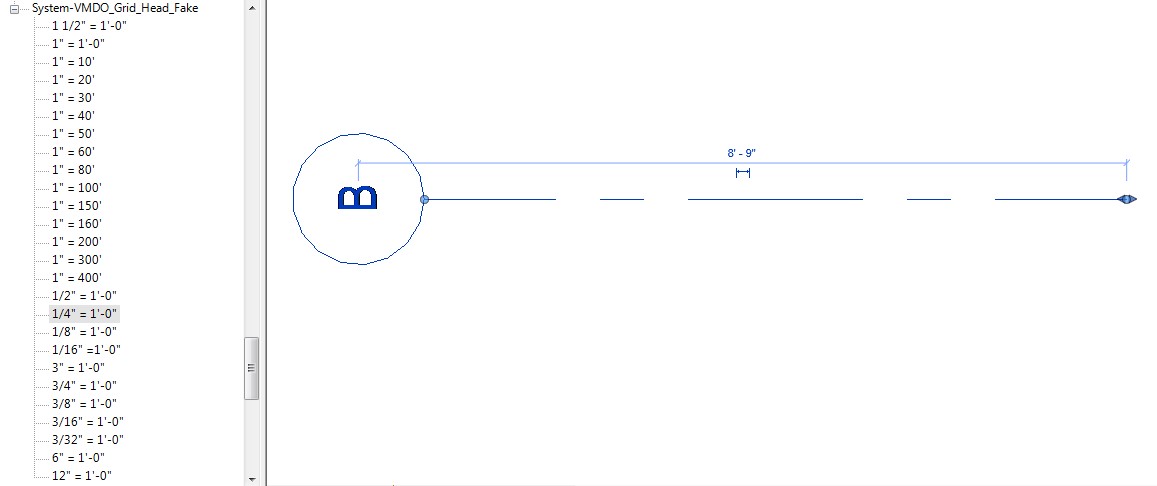
For the grid line length I assigned in instance parameter and the Grid label / name another instance parameter. Great, loaded it into the project and realized we needed the text to rotate with the family to match the real column grid system family: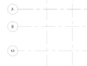
I tested every combination of checking “Rotate with component” & “Keep text readable” in the nested annotation family as well as in the detail item host family. I couldn’t get this to work so I made a second instance of the nested annotation family rotated and gave each one a visibility parameter with a formula preventing the user from keeping them both visible: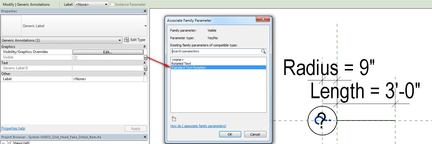
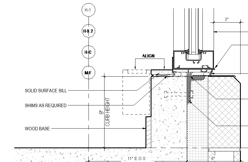
This worked fairly well, but there were two problems discovered. The first is that the nested annotation family text appears bold even though all the properties for the label are identical to the label in the OOTB column grid family. The second problem is that the masking region of the bubble/column label did not mask the real column grid line:
Next, after doing some research about the “shared” option with nested families I tried selecting that checkbox in the nested annotation family: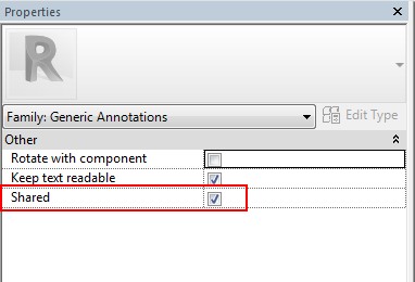
This worked to fix the problem of the bold looking text, but it broke the scaling behavior that is typical of an annotation family. Now the annotation text label resizes with the rest of detail item family when the view scale changes: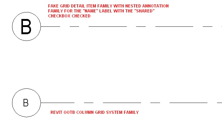
At this point I felt like I was back where I started. So I tried thinking about it with a clean slate, but with the knowledge I now had from the “research” of trying to build the family as a detail item. Here’s what we know:
- An annotation family is what this family wants to be. Then it would be grouped in the project browser with the real grid head family that is used in the column grid system family.
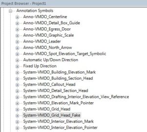
- The only reason we tried a detail item family was to get the grid line stretchable with grips….and we didn’t think this was possible in an annotation family because you can’t create or copy existing reference planes.
- Annotation families scale correctly (always look correct when the view scale changes), get their visibility graphics settings correct (no bold text surprises, no line weight surprises, masking regions work).
Back to google. I found several posts and videos showing a trick where you can copy a reference plane from a view title family into a generic annotation family!! I thought this was the break-though I was looking for. I copied and pasted a reference plane in and was able to copy it to create another, defining the start and end point of the grid line. I created a new subcategory called “Fake Grid Line” so the correct line type could be assigned once loaded into a project. I drew a line on this new subcategory, locking the left end to the left reference plane, and the right end to the right reference plane. Last, I placed a dimension between these two reference planes and assigned it to the parameter “Grid Line Length”.
Loaded it into a project and it looked great……. but when I used the grips to stretch the length of the grid line it did not work as expected. The line length jumped to much longer than the increment I stretched with the grip:
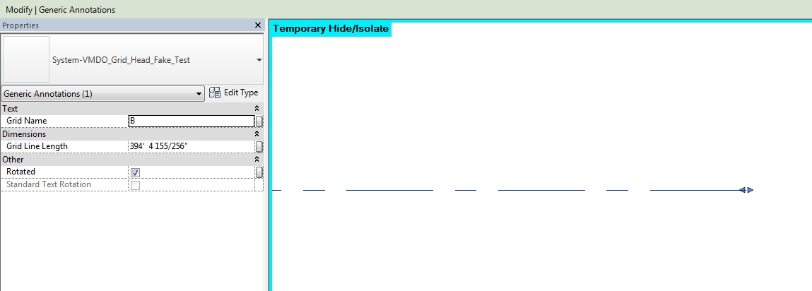
Stretching the grip a very small amount changed the grid line length from 2″ to 394′ + …… WHAT!?!?!?!
Revit must be scaling the small increment that I stretch with the grip based on the view scale…but I can’t figure out what math is making the line 2,364 times longer!?!? So now we’ve got this beautiful fake grid annotation family that will work exactly the way we want on a sheet or a view with scale set to 1:1…which is NEVER where we will need to place it. GREAT.
In the end, I deleted the reference plane and removed the reference plane that made the family stretchable. I kept the instance parameter that adjusted the line length, but constrained the dimension to the line, not the reference plane:
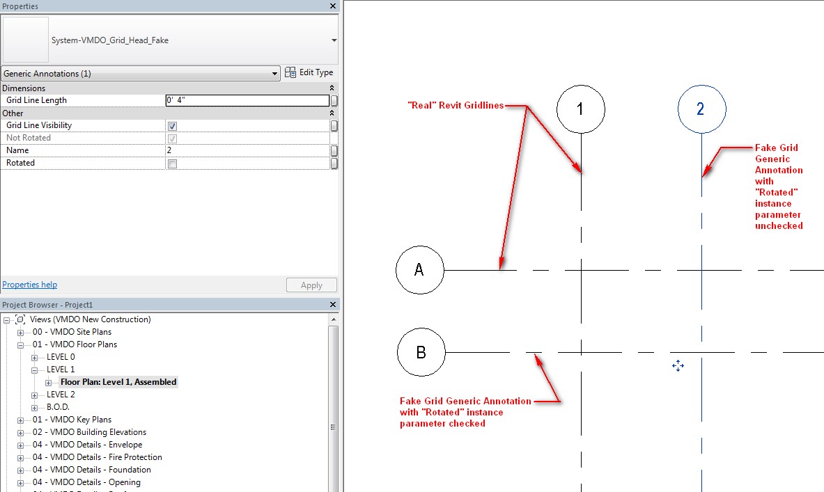
This allows the line length to still be adjustable on an instance basis by typing the desired line length….it’s just not stretchable with grips. Disappointing, but it’s the cost of ensuring the graphics look correct…..
